Now the electricity is going where we want, how do we measure how much of it there is and control its flow? It looks complicated at first, but once you understand how electricity moves, the following terms will flow and make sense.
Voltage (V) is a measure of the “push” of electrons. Think of water flowing in a hose, if you aim it to the sky and increase the pressure, the water pushes higher.
We might also call Voltage the, “Potential difference” and the HIGHER the voltage the greater the potential difference to do work. Your mobile phone uses a 5V USB charger which means that the energy needed is not that high. In contrast, power outlets have a Voltage of 220-240V and mains power lines can have 10,000V to 100,000V travelling through them.
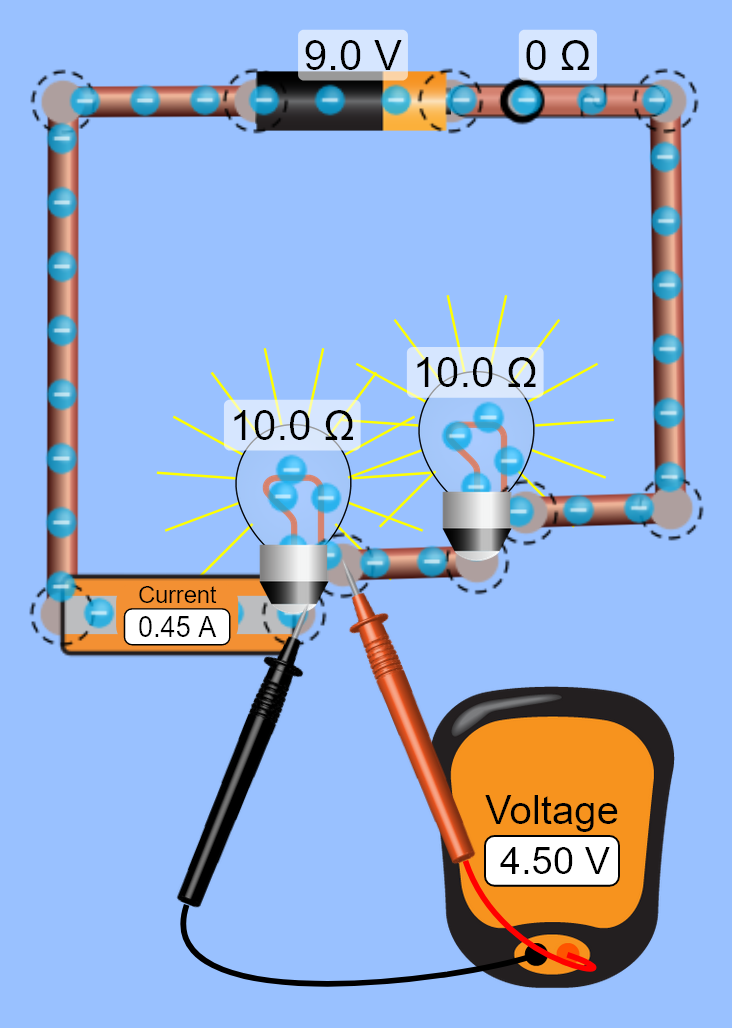
To measure Voltage we use a “Voltmeter” which must be connected in Parallel with the resistor, e.g. light bulb.
Ampere (Amp or A) is the unit of current. In electric circuits this charge is carried by electrons moving through a wire. Think of this as HOW MUCH water is flowing from the tap.
An electric current is the rate of flow of electric charge past a point or region. The Amp’s of a circuit indicate how many electrons are flowing in a circuit. Your phone may have some sort of “Fast charging” feature where it keeps the Voltage the same, however, the Amps vary from 1A, 2A, 5A. Every step up in Amps decreases your charging time by that factor. e.g. if you use an old 2A charger but your phone comes with a 5A, it will take 2.5 times longer to fully charge your phone!
To measure Amps we use a “Ammeter” connected in series with the resistor.
Resistance is the opposition that a substance offers to the flow of electric current. Imagine squeezing the end of a hose to restrict the flow of water, it slows the flow, but increases the water pressure (Resistance Increase = Voltage Increase and Amp Decrease)
Electrical devices that do work are all considered as resistors. The flow of electrons through them can push, turn or heat up. These include electric motors, lights, fans, speakers, monitors, resistors, heaters, computers, etc.
When an electric current of one ampere passes through a component across which a potential difference (voltage) of one volt exists, then the resistance of that component is one ohm. (V=IR)
Activity: The drawings below show analogies of current and potential difference.
a Which diagram represents the current? Which current is greater? Give a reason.
b Which diagram represents the potential difference? Which potential difference is greater? Give a reason.

ACTIVITY: The above examples refer water as an example for how electricity flows. How might you explain electricity using cars on a road? Discuss as a class and draw diagrams in your book from the board.
Making sample circuits (PhET Circuits)
During this topic we’ll get to spend time physically making these circuits and also with the use of Simulations so we can test more complex circuits before we build them. Simulations allow us to predict how a circuit will work before we test them out in the real world. Try setting up the circuits shown below.

Spend some time experimenting with all the tools in this simulation as there will be test using this tool later in the topic.
Quiz time!
You can do this quiz as a revision later in the topic but for now we will do it as a class.
https://quizizz.com/admin/quiz/573298be6a8918854a5476ac/electricity-quiz
